Introduction
Welcome to my first blog post, marking the beginning of an exciting journey! In this post, we’ll explore how to design customized, fully functional, 3D-printable Bead-lock wheels for a 1/10 scale RC crawler truck. My passion for building cars has led me to embark on creating a fully customizable 3D-printed crawler, and this wheel is just the starting point of many more designs to come.
In this guide, I’ll walk you through the design process using Fusion 360, the steps for 3D printing, and the final assembly of the wheel—complete with videos to help you along the way. Whether you’re new to 3D modeling or a seasoned enthusiast, you’ll find something valuable here to help you create your own functional and stylish designs.
What You Will Learn
By the end of this guide, you will learn:
- How to create a 3D model of a Bead-lock rim using Fusion 360.
- Key 3D printer settings and print bed layouts for this project.
- Important considerations before printing.
- Tips for achieving high-quality output.
Tools and Materials You’ll Need
Before diving in, here’s a quick overview of the tools and materials required for this project:
- Fusion 360: A versatile CAD software used for designing the rim.
- 3D Printer and Filament: PLA or PETG is recommended for durability.
- Digital Calipers: For accurate measurements (especially if adjusting for different wheels and builds).
- M3x10mm Countersunk Socket Head Screws: 5 pcs (for assembly).
- M3 Brass Inserts: 5 pcs (for added durability).
- 112mm Diameter RC Tires: Used as the basis for this design.
- Soldering Iron: For inserting the M3 brass inserts.
(Links to these items can be found in the resources section.)
Key Dimensions to Note
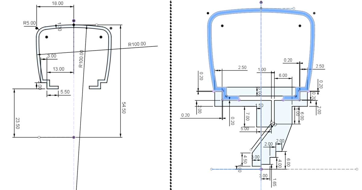
Below is an image showing the critical dimensions needed to design the beadlock rim for the RC tire used in this project. If you’re using different tires, be sure to measure their dimensions accurately.
For this design, the tire’s thickness is 1.5mm, so I used a 1.3mm inner rim thickness to maximize grip. The soft rubber of the tire makes this adjustment crucial for a secure fit.
Left side of the dimension image represents the cross section of the tire and right side of the image shows the cross section of the rim including three parts. Blue color part it tire.
Two Types of Designs Available
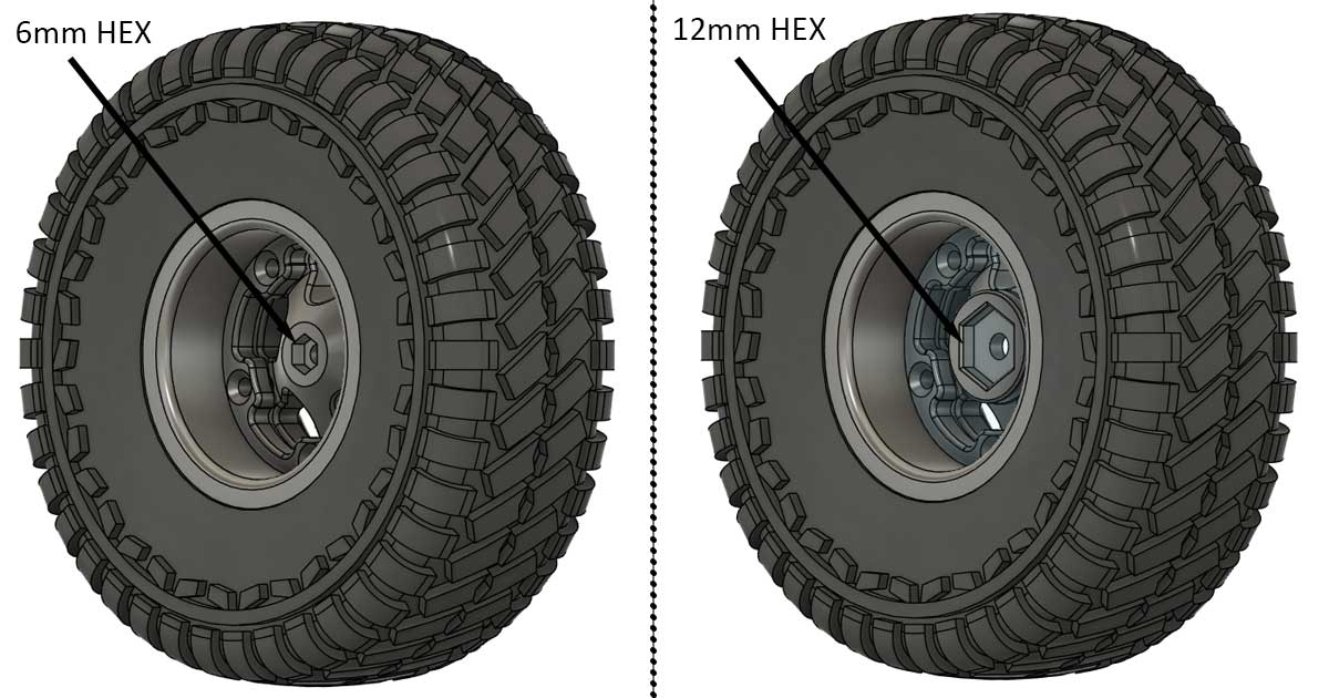
In the downloadable section, you’ll find two files: one with a 12mm hex nut support and another with a 6mm hex nut support.
What Is a Hex Nut in RC Wheels?
Every RC car uses a hex nut to attach the wheel to the axle, ensuring rotation. The hex nut size varies, but for most 1/10 scale RC cars, a 12mm hex nut is standard. If you’re designing for an existing RC car, download the 12mm hex nut support file.
Since I’m working on a fully custom design, I opted for a 6mm hex nut size. This allows for additional room inside the rim, which will be useful for integrating a CV joint in future designs (spoiler alert!).
Modeling the Wheel
I’ve created a detailed video series covering the entire modeling process in Fusion 360. Here are the links:
Video 1: Creating the Tire
Video 2: Designing the Rim
Specific Features in the Design
1. Tight Inner Fit for the Rim
To ensure a secure lock between the tire and rim, the inner part of the rim is designed with no tolerance. This tight fit helps the assembly endure tough terrains.
2. Fillets for Strength and Grip
Fillets were added to the beadlock edges, even though the tire doesn’t have them. This design choice strengthens the sidewall of the rim and increases the contact surface area between the rim and tire, improving grip.
3. 1mm Space Between Front and Back Rims
A small gap ensures the two parts can be tightened securely using five screws, enhancing the grip between the tire and rim.
4. Why Only Five Screws?
Using five screws balances strength and aesthetics. A sixth screw would reduce wall thickness below 2.4mm, compromising durability. Four screws would lack visual appeal.
5. Tolerances
I designed it with a 0.1mm tolerance based on my printer’s capabilities. Adjust according to your printer’s tolerance.
6. Why Three Parts?
The design uses three separate parts that eliminate the need to glue the tire. This makes it easier to reuse or change the design when needed, adding flexibility and convenience.
Preparing for 3D Printing
Exporting STL Files
Export each component of your model as separate STL files in Fusion 360:
- Go to File > 3D Print.
- Select the body to export.
- Choose STL (ASCII) format.
- Save to your desired location.
Printer Settings
- Layer Height: 0.2mm (for quicker prints).
- Brim: 3mm (to ensure better adhesion to the print bed).
- Wall Thickness: 1.2mm (for added strength. It will print 3 wall lines if you use 0.4mm nozzle).
- Infill: 20% (adjust if you prefer a sturdier build).
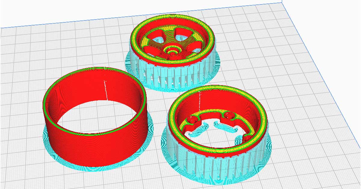
Ensure the orientation matches the provided image for optimal strength and surface finish.
Assembling the Parts
The following video explains the assembly process, including how to insert the M3 brass inserts using a soldering iron.
Tips for Success
- Material Choice: Use strong materials like PETG or PLA for durability.
- Accurate Measurements: Ensure dimensions align with your chosen tires.
- Layout Precision: Follow the suggested print layout with at least a 3mm brim.
- Printer Settings: Use a heated bed at 60°C and a nozzle temperature of 205°C (for PLA).
Video : Assembly Video
Troubleshooting
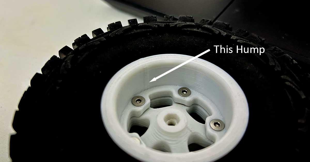
Issue: Small Hump in the Printed Wall
During printing, I noticed a bump on some parts caused. Please follow the below image. After analyzing the slicer software, it appears to happen at when the layer transitions to the next layer. If you have a solution, please share it, and I’ll test it out and let you know the results!
Resources
What’s Included in the Download:
- 12mm Hex Nut Support File: Ideal for most standard 1/10 scale RC cars.
- 6mm Hex Nut Support File: Designed for custom builds with additional room inside the rim.
Both models can be found from the following link : Printables Link
Links to accessories
- 112mm Diameter RC Tires: Get Here
- M3x10mm Countersunk Socket Head Screws: Get Here
- M3 Brass Inserts: Get Here
Conclusion
Designing and building your own RC car wheel is both fun and rewarding. With Fusion 360 and some creativity, you can create something truly unique. I’d love to see your designs—share them in the comments or tag me, Innovativegeek, on social media!
Happy Designing and Printing!

0 Comments